Hidden Hidden Hidden Hidden


SENSOR CALIBRATION
REFERENCE > ADVANCED TECHNIQUES >


Sensor Calibration Overview

Sensor Calibration is done by the end user to improve sensor measurement accuracy. The end user provides a known stimulus to the sensor, records the measured value, and then has the software map this value to the expected value. This is done either with one point (e.g. at 0 stimulus) or two points (e.g. 0 and maximum input). Alternatively, if you are interested in instruNet internal voltage measurement calibration, click here.

Standard or End User Units

Standard units are the units typically associated with a sensor. For example microVolts (μV), milliVolts (mV) and Volts (V) are considered Standard units with a Voltage sensor. Or Kg, LBs, and Newtons are considered Standard units with a Load Cell force sensor.

Alternatively, End User Units involve the mapping of Standard units to one's own units. For example, a sensor that converts levels of light (e.g. lumens) to volts, would establish lumens as the End User units.

One sets and calibrates End User units via the Mapping dialog; whereas one calibrates Standard units via the Quick Setup dialog.


Calibration of Standard units in Quick Setup dialog

If you are interested in calibrating a strain gage or load cell sensor, click here; otherwise, continue reading. Sensor calibration involves applying one or two known stimuli, measuring the associated voltage(s), and applying the measured mapping to future measurements. The following steps perform one-point or two-point calibration of Standard units via the Quick Setup dialog box.

  1. Make sure you are using instruNet software version ≥ v3.7 (file "iNet32.dll"). To check your version, select ABOUT in the instruNet World HELP menu; and to update for free, click here.
  2. Set up your sensors and save your settings in a .prf file via the SAVE button in the NETWORK page (e.g. with file name "settings.prf").
  3. Find your channel in the NETWORK page and press it's Quick Setup button.
  4. Apply a small known stimulus to the sensor and set the Low Calibrate field to this value. For example, if you apply 0.0mA to a 0-to-20mA current sensor and are displaying mA units, then set Low Calibrate field to 0.0.
  5. Press the LOW CALIBRATE button to measure and lock-in the voltage associated with this value.
  6. Optionally, do the same with a 2nd HIGH CALIBRATE point. For example, one could apply 18mA to the 0-to-20mA current sensor, set the High Calibrate field to 18.0 and press the HIGH CALIBRATE button.
  7. Try several different stimuli and see if they agree with the measured values. If they don't, click here.
  8. Press the SAVE button in the NETWORK page to save your new calibration values in a .prf settings file (e.g. in file "calibrated settings.prf").


One-Point ZERO (0.0) Calibration of End User Units in Mapping dialog

If you are interested in calibrating a strain gage or load cell sensor, click here; otherwise, continue reading.

One-point zero sensor calibration involves applying 0.0 stimulus to your sensor (e.g. 0.0°C to temperature sensor), measure, and then instruct the software to add an offset to all readings such that 0 stimulus causes you to measure 0.

Pressing the Point #1 Calibrate button in the Mapping area (and mapping a newly measured value to 0.0) will effect both Offset and Scale, and this is different from Zero calibration described here (which effects only Offset). If you feel a great urge to press the Calibrate button in the Mapping dialog, then please instead refer to two-point calibration.

The following steps enable the end user to do one-point zero calibration, which causes a fixed offset to be added to all future readings.

  1. Make sure you are using instruNet software version ≥ 3.4.0.5 (file "iNet32.dll"). To check your version, select ABOUT in the instruNet World HELP menu; and to update for free, click here.
  2. Set up your sensors and save your settings in a .prf file via the SAVE button in the NETWORK page.
  3. Apply 0 stimulus to sensor (e.g. place temperature sensor in 0°C ice bath, apply 0 Kg to load cell)
  4. Click on your channel in the Network page and press the SENSOR REPORT button.
  5. Identify the "Current Value in .. native internal units (Vinit has been applied yet Mapping Has Not been applied)" and write this down on a piece of paper, we will call this "X".
  6. Click on your channel in the Network page and select Mapping in the Settings menu of the Channel Options dialog.
  7. Negate your number X (i.e. -X) and then add this to the Offset parameter (upper-right corner of Mapping area). For example, if Offset was set to 3.0 and you measured 2°C when applying 0°C, then update the Offset parameter to +1.0°C (3 + -2 = 1). For more information on the Mapping dialog box, click here.
  8. To lock in your new value, click the UPDATE button or the OK button.
  9. Try several different stimuli and see if they agree with the measured values. If they don't, click here.
  10. Press the SAVE button in the NETWORK page to save your new Mapping values in a .prf file. When doing measurements in the future, use this file.


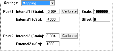
Two-Point Calibration of End User Units in Mapping dialog

Two-point sensor calibration involves applying two different stimuli to the sensor, measuring the response to each, and then telling the software to map the original values to the new calibrated values. The following steps enable the end user to do this two point calibration.

  1. Set up your sensors and save your settings in a .prf file via the SAVE button in the NETWORK page.
  2. Click on your channel in the Network page and select Mapping in the Settings menu of the Channel Options dialog. If you do not see the Calibrate button, make sure you are using instruNet software version ≥ 3.5.0.1 (file "iNet32.dll"). To check your version, select ABOUT in the instruNet World HELP menu; and to update for free, click here.
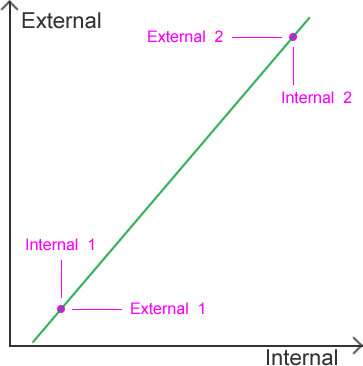
  3. The mapping area controls the mapping of internal units to external units.

    External units are what the user sees.

    Internal units are the native units used by the sensor. These are "Volts" for a Voltage sensor, "ohms" for a resistance, "Amps" for a current source, "C" for a temperature sensor, "Kg" for a Load Cell, "Strain" for a strain gage and "g" for an accelerometer.

    For more details on Mapping, click here.
  4. Apply a small known stimulus to the sensor and set the External_1 parameter to this value in Displayed external engineering units. For example, if you apply 0.0Kg to a 0-to-100Kg load cell (which measures weight), then set the External_1 parameter to 0.0.
  5. Now press the Point#1 Calibrate button. This will cause the system to measure the stimulus in Native internal engineering units, and place this newly measured value into the Internal_1 field.
  6. Apply a large known stimulus to the sensor and set the External_2 parameter to this value in Displayed external engineering units. For example, if you apply 80.0Kg to a 0-to-100Kg load cell, then set the External_2 parameter to 80.0.
  7. Now press the Point#2 Calibrate button. This will cause the system to measure the stimulus in Native internal engineering units, and place this newly measured value into the Internal_2 field.
  8. The text displayed next to the measured value is referred to as the "Units Label" (e.g. "Kg", "Volts", "psi"). You can change this at any time by entering the Channel options dialog box and selecting General in the Settings menu. This text does not effect the values, it is only a label.
  9. Try several different stimuli and see if they agree with the measured values. If they don't, click here.
  10. Press the SAVE button in the NETWORK page to save your new Mapping values in a .prf file. When doing measurements in the future, use this file.

Two-Point Calibration Example
Suppose an LVDT sensor produces a current proportional to linear position along a shaft, where 0.0041 Amps corresponds to 0.0 mm and 0.023 Amps corresponds to 20.0 mm. Subsequently, one would:

  • Set up instruNet to measure current
  • Change the units label from "Amps" to "mm" (millimeters) in the GENERAL settings area.
  • Set the Mapping parameters as follows: internal1 = 0.0041 (Amps), external1 = 0 (mm), internal2 = 0.023 (Amps), external2 = 20 (mm).


See Also