Hidden Hidden Hidden Hidden


INSTRUNET WORLD CHANNEL SETUP "NETWORK" WINDOW
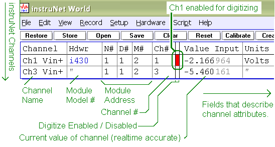
SOFTWARE > INSTRUNET WORLD SOFTWARE (iW) >

Overview
The Network Page is used to view and modify Fields that control all Analog, Digital, and Timer I/O channels within an instruNet network.  These Fields do things like define the cut-off frequency of a digital low pass filter, set the range of a voltage input, or define the type of sensor that is connected to the input.

Surfing The Net
After starting the instruNet World application the Network Page is selected by clicking the Network tab at the bottom of the instruNet World window.  Your Network Page will resemble the above illustration, although your rows and columns may differ depending on what is attached to your network.

Each row corresponds to a Channel (e.g. typically one sensor is attached to each voltage input channel), and the columns are used to display the settings of Fields that pertain to each Channel.  The horizontal scroll bar is used to scroll through the Fields, and the vertical scroll bar is used to scroll the Channels.

Modifying Fields
To change a Field, simply click on its cell. The Channel Setup dialog will pop open and it is here that one can view and modify all Fields within the network.  Typical networks will house thousand of Fields yet their default values, in most cases, will suffice (relax !). 

Channels
The below illustration shows an expanded view of the Network Page.  The Channel names appear in the left-most column, and the real-time values of each channel are under "Value Input".  The "network address" (i.e. network number, device number, and module number) of each channel is shown in column 2.  The first channel in the first module of the first device attached to the first Controller will have a physical network address of {1,1,1,1}.  The table header is optimized for the upper-most visible channel, and therefore may change slightly when scrolling vertically.

Turning A Channel On
To "enable" a channel for digitizing (so you can see its signal in the Record Page), one must click on the small vertical rectangle after the network address.  It will turn RED to indicate that the channel will be digitized when the Start button is pressed in the Record Page.  Clicking it again will  turn it "off".  The below illustration shows channel Ch1 as being "turned on".

Saving Your Configuration
The buttons at the top of the Network Page are used to save Field settings to disk, load them from disk, Clear them to their default values, and to Reset hardware.  In a typical session, the user will modify several Fields (e.g. turn on 2 channels and set their filter and sensor parameters), save these settings to disk via the Save button, exit instruNet World, run instruNet World a week later, and reload these settings via the Open button.  When the state of instruNet World is saved to disk, you are saving the Fields that have changed from their default values.  When you load the state back in, instruNet will first set all Fields to their default values, load the file, and then update the Fields that were changed. Therefore, these "state" files are typically small (e.g. several KB).  In fact, you can open these text files with a Word Processor or Spreadsheet program to glean a sense as to how instruNet internally stores Fields settings.  instruNet keeps all state in Fields, therefore, it is not necessary to save anything else (except waveform data) in order to get you back to where you were.  Saving waveform data is done independently via the Save and Open buttons at the top of the Record Page.  The Network Page manages Fields, whereas the Record Page manages waveforms.

Reconnecting With A Changed Network
If your instruNet Network changes (e.g. you physically pull out 1 device, and then install 2 more), the stored Field settings may no longer apply to your new network. instruNet does its best to "reconnect" and will alert you to any discrepancies, yet it is always a good idea check your settings after physically changing your network.  Typically, adding hardware will not cause discrepancies, since you are adding Fields that will be kept at their default values when you load in the settings to "other" fields.  However, if you physically reduce your instruNet network (or replace one device with another), a settings file may try to set a field that no longer exist, and in this case, instruNet might show an alert that states it is having a little trouble.

Buttons
The Network Page has the following buttons at the top of the window:

  Restores the state of all Fields that existed when the Store button was last pressed.  Restore loads a .prf settings file that was last saved when you pressed the Store button.  Restore and Store are very similar to Open & Save, except Open & Save show a File dialog that enables the user to pick the file name & directory; whereas Restore & Store always go to the same file & directory and do not bother the user with file issues.

  Saves an instruNet setup .prf file to disk that contains the state of all Fields.  This preference file is stored within the end user documents directory, and is reloaded by pressing the Restore button.  File Save and File Open dialogs are not used since the file name and directory are always the same. The .prf file is save at "MyDocuments\instrunet\end user\instruNet_Store_And_Restore_settings.prf" when using iNet32.dll ≥ v3.4.

  Saves a .prf instruNet setup file to disk that contains the state of all Fields, scripts, and user defined objects.  The user specifies the file name and location within the standard File Save dialog.

  Loads a .prf instruNet setup file from disk that contains the state of all Fields, scripts, and user defined objects.  The user must pick a previously stored settings file via the standard File Open dialog.

  Delete channel settings, scripts, and user defined objects (e.g. popup menu, edit field, etc).

  Same as the Clear button, yet also Resets all instruNet hardware.

  Calibrates all instruNet hardware.  To set up this button to also balance strain gages and load cells at 0 µStrain (or 0 Kg force), press the Setup button in the Record page, press the Calibration button, set the Cal Button field to Bal Gages, and then exit the dialogs. For more details on Calibration, click here.