Hidden
Hidden
Hidden
Hidden
Hidden
Hidden
Hidden
TROUBLESHOOTING i420/i430 VOLTAGE MEASUREMENT
ERRORS DUE TO BLOWN IC
For details, please click the below links:
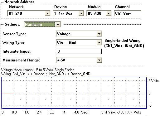
Determining If Your IC Is Blown If your analog measurement is not correct, then it could be due to incorrect software setup, incorrect wiring, or a blown IC. To determine if it is a blown IC, place a wire between GND and Ch1 (to apply 0V), run instruNet World software, open the channel dialog box for Ch1 (for that i4xx card) and look at the measured voltage on the default settings (+-5V range, Single-Ended Wiring). Recall that Single-Ended involves measuring the voltage between GND and the voltage input terminal and is indicated with "Vin - GND" in the Wiring menu. The system should measure a voltage between -0.005V and +0.005V. If you see anything else (e.g. +-50mV to +-200mV), then that is wrong and the IC attached to Ch1 is probably blown. This would be Max4709ese (U821) if working with the i420 and Max4708ese (U6) if working with the i430. There are two IC's on each card attached to voltage input pins. The above instructions test the first IC. To test the second IC on the i430, attach 0V to Ch2 (wire between GND and Ch2) and then monitor the Ch2 voltage via the channel dialog (+-5Vrange, "Vin-GND" wiring). If you see a voltage other than ≤ +-5mV, then Max4708ese (U7) is blown. To test the other IC on the i420, attach 0V to Ch9 (wire between GND and Ch9) and then monitor the Ch9 voltage via the channel dialog (+-5Vrange, "Vin-GND" wiring). If you see a voltage other than ≤ +-5mV, then Max4709ese (U822) is blown. In some cases, both IC's are damaged at the same time. The below picture shows the channel dialog doing single-ended +-5V measurement:
There are two ways to fix an IC. One is to return hardware to your instruNet supplier for repair; which involves time and cost. Another is to fix in one's laboratory by de-soldering the blown IC and installing a new IC. These IC's are available from www.digikey.com; which ships directly to the USA, Europe, Asia and China. To buy from digikey, please click on Max4709ese (i420) or Max4708ese (i430). For videos on rework, please see: IC Removal and IC Soldering.
|
 The i420/i430 voltage input pins attach directly to